Update: The series is complete. For more articles and information, visit these other posts:
Part 1: Identification and Task List
Part 2: Intake Checks
Part 3: Capacitor Replacement
Part 4: Resistors and Controls
Part 5: First Power-Up
Part 6: Socket Replacement and First Alignment
Part 6.5: Diagnosing an RF Intermittent
Part 7: Conclusion
I’ve frequently posted snips of information about antique radio restoration and repair, anecdotes and photos and such – but that’s not a very comprehensive look at the hobby. A new radio to repair has just arrived on my bench from a client, and his radio has the honor of serving as the feature in this upcoming series of blog posts, Repairing Antique Radio Electrics from Start to Finish.
In this first post, I’ll be identifying the major components of an antique radio and talking briefly about their features. Some terms that may be unfamiliar are linked to their articles in Wikipedia, if you’re interested in further reading.
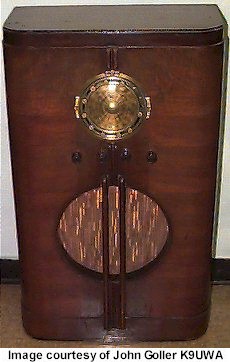
The radio in question is a 1937 Grunow model 586589. Grunow radios were produced by General Household Utilities Co. and this example is excellent for demonstration because of its simple and straightforward design: 5 tubes, with AM and Shortwave reception. Not a lot of bells and whistles, but a very solid radio with a reputation for quality. And quite pretty when installed in the cabinet, too! (photo from Radio Attic Archives)

Freshly unboxed, the chassis and speaker (not pictured) arrived. They were extremely well-packed, double-boxed and with protective cardboard over areas that could be damaged by punctures.

Grunow radios are known for their beautiful Teledials. The entire dial face rotates to indicate the station at the 12 o’clock position on either band, and the station markers can be moved to indicate positions of favorite stations on the dial – a primitive preset function. I obtained the schematic for the radio from Nostalgia Air which is always helpful when working on a radio. Radio schematics for the old radios are in the public domain and scans can be readily found online.
Here is the chassis from a few more views, and then I will point out some of the important components.


This radio uses five tubes. Two of them are not pictured (the 4- and 6-pin tubes on the left of the top-view photo), and the remaining tubes are the 6A7 Modulator/Oscillator, 6D6 IF Amplifier and 75 Detector/First Audio. The missing tubes are the power rectifier, type 80, and the power output tube, type 41 or 42.
Let’s identify the top-side components:

- Power Transformer: Takes the incoming electricity from the wall and converts it to levels suitable for use in the tube radio. Radio tubes require a very high voltage on the plate (100-300 volts typically), called the “B” voltage, and one or many smaller voltages (5-12V typically) for the “A” voltage to power the tube heaters.
- IF Transformers: In this type of radio (a superhetrodyne), these Intermediate Frequency (IF) transformers pass signal from one stage to the next at a tuned frequency usually around 455KHz (in this case 465KHz). Because these transformers only need to be tuned once (contrast with a Tuned Radio Frequency receiver) they can be more efficient and have fewer reliability issues.
- Filter Capacitors: These passive electronic components filter the incoming electricity after it has been rectified and converted to DC by the type 80 power rectifier.
- Tuning Gang: The tuning gang is another type of capacitor – except this one is variable. Movable metal plates slide in and out of fixed metal plates with a very tiny air gap, changing its capacitance and thus changing what station the radio is tuned to.
- Controls and Dial: These knobs and display are used to control the radio (on-off-volume, AM/Shortwave, Tone [equalizer] and Tuning.)
- Speaker Wires: Connect to the speaker field coil and speaker output transformer.
There are also components under the chassis, too. Let’s take a look at the bottom. I find it’s easy to use C-Clamps and pieces of wood to raise the chassis above the work surface, so it isn’t resting on any of the components on the top. They’re not “fragile” per se, but supporting the radio’s full weight on a couple of rivets isn’t the best idea – not to mention, this raises it up another foot for a more ergonomic working posture while standing.

Now, with labels:

- Antenna In: connections for the radio’s antenna to receive signals.
- Capacitor: A passive component, these wax paper capacitors age, dry out and leak causing short circuits and must all be replaced.
- Resistor: A passive component, these carbon resistors can absorb moisture as they age and increase their resistance, potentially changing the behavior of tubes or choking off the flow of electricity to circuits.
- Tube Socket: The bottom of the tube plug-in, with connections to the rest of the components.
- Bias Cell: A primitive early battery about as powerful as a watch battery, used to place control voltages on tubes.
- Oscillator Coil: In conjunction with the oscillator tube, the 6A7, this coil forms part of the tuned circuit that resonates at 465KHz to provide the intermediate frequency fed into the oscillator.
- Antenna Coil: Provides loading for the antenna and reduces parasitic effects to improve performance.
